Cryogenic Treatment of Aluminum Die Castings
Cars are major energy consumers, accounting for more than 13% of carbon emissions. According to statistics, for every 100 kg reduction in the weight of a vehicle, carbon dioxide emissions can be reduced by about 5g/km; at the same time, for every 10% reduction in vehicle weight, power consumption can be reduced by 5.5%; cruising range can be increased by 5.5%, and daily wear and tear costs can be saved by 20%. Therefore, weight reduction is of great significance to the development of the automobile industry. Aluminum alloy is currently the most popular lightweight material, and die-cast parts have the advantages of high quality, good mechanical properties, high efficiency, and are suitable for mass production. Therefore, aluminum alloy die-cast parts are widely used in automobile bodies, wheels, chassis, battery cases, etc. However, due to the fast speed and short time of the die-cast process, it is difficult for the gas in the die-cast cavity to escape in a short time and is thus trapped in the die-cast part. As a result, it is easy to produce holes during conventional heat treatment, which greatly reduces the mechanical properties of the die-cast part, limiting the wide use of die-cast aluminum alloys.
Cryogenic treatment is a method of treating materials below -130°C, using liquid nitrogen as a medium, which can change the microstructure of the material and thereby improve the mechanical properties of the material. At present, cryogenic treatment, as an important strengthening method, has been widely used in steel. In recent years, affected by the global emphasis on energy conservation and environmental protection, research on cryogenic treatment for aluminum alloys has become a hot topic. Guirong Li and others conducted cryogenic treatment on aluminum-based composite materials and aluminum-silicon alloys and found that cryogenic treatment can promote the precipitation of the second phase and improve the mechanical properties of the material by hindering dislocation movement. Zhisheng Wu and others conducted cryogenic treatment on 5A06 aluminum alloy welded joints and found that after cryogenic treatment, the grain structure of the welded joint was refined, holes were reduced, and the matrix density was increased. Ding Chen and other people performed cryogenic treatment on aluminum alloys of different compositions and proposed that the volume shrinkage effect induced by cryogenic treatment plays an important role in improving mechanical properties. Ye Yang and others performed cryogenic treatment on aluminum-silicon alloy and found that cryogenic treatment can passivate the iron-rich phase in the structure, greatly reducing the splitting effect on the matrix, and effectively improving the mechanical properties of the aluminum alloy. Jianzhong Zhou and others conducted cryogenic treatment on laser shot-peened aluminum alloy and found that cryogenic treatment can inhibit the dynamic recovery of dislocations, generate high-density dislocations in the sample, and produce a good structural strengthening effect. In short, cryogenic treatment has different strengthening effects on aluminum alloys with different compositions, and there is no consensus on the strengthening mechanism. There are also studies on the combined use of traditional heat treatment methods such as solid solution and aging with cryogenic treatment and found that the synergy of the two can further improve the mechanical properties of aluminum alloys, but the treatment process is more complex and the treatment time is longer. At present, there are few studies on the cryogenic treatment of die-cast aluminum-silicon alloys, and the influence of cryogenic time on die-cast aluminum-silicon alloys is still unclear.
1. Test materials and methods
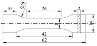
The test material is die-cast aluminum-silicon alloy, and its composition is tested with a German Bruker S1-TITAN handheld spectrometer as shown in Table 1. The test samples are divided into 5 groups. The specific processing technology and sample numbers are shown in Table 2. The ingot was processed into a cube of 10 mm × 10 mm × 5 mm and a tensile specimen as shown in Figure 1 using wire cutting. Cryogenic treatment is carried out in liquid nitrogen cryogenic tanks. The MTS-DDL100 electronic universal testing machine was used to test the mechanical properties of each group of samples. The tensile rate was 1 mm/min, and each group of samples was tested three times and the average value was taken. Use the FM-ARS900 microhardness tester to measure the microhardness. Each group of samples is tested at 5 points and the average value is taken.
Table 1 Chemical composition of die-cast aluminum-silicon alloy wB/%
| Al | Si | Cu | Zn | Fe | Mg | Mn | Ni | Cr | Fe | Mg | Other elements |
| 84.90 | 10.42 | 2.10 | 0.99 | 0.93 | 0.23 | 0.20 | 0.06 | 0.05 | 0.93 | 0.23 | The rest |
Table 2 Cryogenic treatment of die-cast aluminum-silicon alloys
| Groups | Sample status | Processes |
| A | Cast state | None |
| B | Cryogenic treatment for 6 hours | Cryogenic treatment at -196°C for 6 hours |
| C | Cryogenic treatment for 12 hours | Cryogenic treatment at -196°C for 12 hours |
| D | Cryogenic treatment for 24 hours | Cryogenic treatment at -196°C for 24 hours |
| E | Cryogenic treatment for 48 hours | Cryogenic treatment at -196°C for 48 hours |

Figure 1 Shapes and sizes of tensile specimen
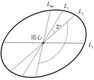
After the metallographic samples were ground and polished, the surface was etched with HF reagent with a volume fraction of 0.5%, and the Observer.Z1m Zeiss optical microscope (OM), HitachiSU-1510 scanning electron microscope (SEM) and electron backscattering (EBSD) were used to observe the microstructure of the sample. Image-Pro Plus image analysis software was used to perform statistical analysis on the composition phases of die-cast aluminum-silicon alloy. Among them, the calculation method of the average particle size of the α-Al phase is shown in Figure 2 and formula (1).
The calculation method is as shown in formula (1):

In the formula, Li is the diameter size passing through the center of mass. D is the average grain diameter: in any grain, the average length of 90 line segments passing through the grain center of mass at intervals of 2°.

Figure 2 The schematic diagram of the calculation method of the average particle size