Optimizing Aluminum Alloy Motor Housings for New Energy Vehicles
The global energy and environmental crisis have prompted the upgrading of international automobile technology, which has brought major strategic opportunities for China's new energy, especially the independent innovation of electric vehicles. As a key component of new energy vehicles, the aluminum alloy motor casing has a complex structure and a requirement for high performance. The aluminum alloy motor casing for a new energy vehicle from a motor company is introduced in this article. The aluminum alloy motor casing is made from ZL101A and weighs 24kg. There are multiple bosses on the outside of the casting. The thickness of the upper side wall is 27.5mm, and the thickness of the lower side wall is 32mm. There is a spiral channel with a width of 8.5mm in the middle side wall, as shown in Figure 1. The inner cavity of the casting, the upper and lower end faces and the end face of the boss are all processed, and there must be no defects such as air holes, shrinkage porosity, and slag inclusions. Air tightness is required to be greater than and equal to 0.6MPa and there should be no leakage.
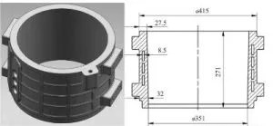
Figure 1 Motor housing castings
1. The original process plan
The upper and lower sides of the casting and the outer boss are thick-walled areas, which will generate hot spots in the solidification process of the casting, while the middle channel is a thin-walled area. The wall thickness difference of castings is great, so it is difficult to achieve sequential solidification; defects such as shrinkage cavities and shrinkage porosity are prone to occur. According to the structural characteristics of the casting, the original plan adopts low-pressure casting, the outer shape and inner cavity use metal molds, and the spiral water channel uses sand cores; the inner side has four side risers, and the bottom is equipped with a cross runner, as shown in Figure 2.
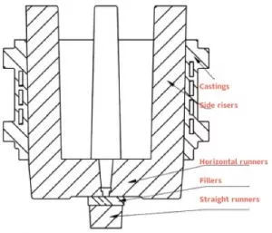
Figure 2 The original process gating system
1.1 Simulating the original scheme
The original scheme is simulated, and the solidification process is shown in Figure 3. The casting started to solidify at 22 seconds, and the casting was completely solidified at 292 seconds. In the solidification process, hot joints are formed in the thick-walled area of the casting, and the feeding channels are interrupted at parts A, B, and C, forming a closed liquid isolated area. Sequential solidification has not been achieved for the casting and tends to form shrinkage porosity.
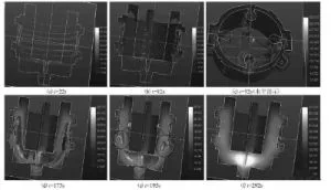
Figure 3 The solidification process of the original scheme
1.2 Problems in actual production
After some castings are processed, a shrinkage cavity appears in the inner cavity and end surface corresponding to the boss (Figure 4 and Figure 5), and the rejection rate is high. Because the shrinkage of the four side risers on the inner side is hindered, it is difficult to demould the iron core during casting production, and the production efficiency is low.
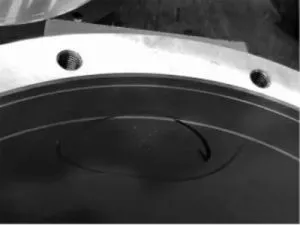
Figure 4 Defects in the inner cavities
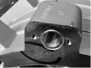
Figure 5 Defects in end face
2. Optimizing the scheme
As shown in Figure 6, the original casting has a great difference in wall thickness, and A, B, C, D, and E are five thick-walled areas. Among them, position A is not conducive to setting riser feeding, and the heat joints formed by the combination of positions B, C, D, and E with the riser exceed the feeding capacity of the riser, and the temperature gradient between the heat joint and the riser has not been established. Sequential solidification is difficult to achieve. Moreover, cast alloys have a critical wall thickness. When the wall thickness of the casting exceeds the critical wall thickness, the strength of the casting does not increase proportionally with the increase in the wall thickness, but will decrease significantly. Therefore, with the consent of the user, the structure of the thick-walled area of the casting is slightly changed, and the weight is reduced to reduce the thermal joint in the solidification process of the casting. The optimized casting is shown in Figure 7.
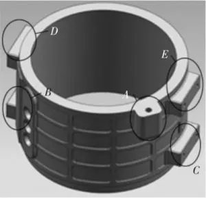
Figure 6 Original castings
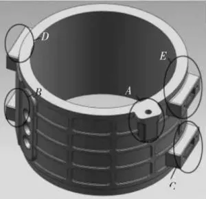
Figure 7 Castings after optimization
According to the simulation results, for the interruption of the feeding channel at the intersection of the runners at B and C, the runners are moved upwards to directly connect with B and C, which also reduces the distance between the horizontal runners and the upper end of the casting and shortens the feeding distance required by the riser. Since the thermal joints at D and E are reduced after the weight of the casting is reduced, changing the four side risers to subsidies with inflection not only facilitates the solidification sequence of the casting from top to bottom, but also reduces the volume of the gating system and shortens the solidification time. It is also conducive to demoulding, which can greatly improve the process yield and production efficiency. The gating system after optimization is shown in Figure 8.
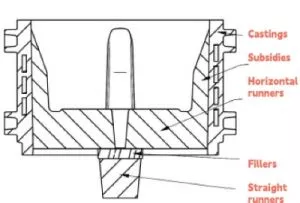
Figure 8 Optimized gating systems
2.1 Simulating the optimized scheme
The optimized scheme is simulated, and the solidification process is shown in Figure 9. In the solidification process, the casting forms a feeding channel through the subsidy, the runner and the sprue, and the expansion angle of the solidification is always toward the direction of the runner, effectively establishing a temperature gradient between the hot joint and the riser, and realizing sequential solidification.
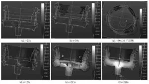
Figure 9 The solidification process of the optimized scheme
2.2 Production Verification
Judging from the production verification, the solidification time of the casting is reduced, and the demoulding is easier than the original solution. There is no casting defect after X-ray flaw detection. After the casting is processed, the machined surface is dense and free of defects, and the air tightness test is qualified.
The casting with the gating system in the original scheme is 47kg; the process yield rate is 51%, and it takes 20 minutes to produce one piece. The optimized scheme has a casting with a gating system of 35kg; the process yield rate is 69%, and it takes 15 minutes to produce one piece. For 1 ton of aluminum alloy liquid, the production time is 7 hours. The original plan can produce 21 pieces, and the optimized plan can produce 28 pieces. The optimization scheme has greatly improved the process yield and production efficiency, and reduced the production cost. The casting produced by the optimized scheme is shown in Figure 10, and the finished product after processing is shown in Figure 11.
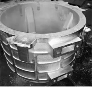
Figure 10 Castings produced by the optimized scheme
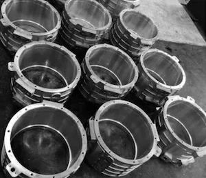
Figure 11 Finished product after processing
This scheme was adopted to produce more than 1,000 pieces, with less than 40 unqualified products, and the pass rate of castings was over 96%.

Figure 1 Motor housing castings
1. The original process plan
The upper and lower sides of the casting and the outer boss are thick-walled areas, which will generate hot spots in the solidification process of the casting, while the middle channel is a thin-walled area. The wall thickness difference of castings is great, so it is difficult to achieve sequential solidification; defects such as shrinkage cavities and shrinkage porosity are prone to occur. According to the structural characteristics of the casting, the original plan adopts low-pressure casting, the outer shape and inner cavity use metal molds, and the spiral water channel uses sand cores; the inner side has four side risers, and the bottom is equipped with a cross runner, as shown in Figure 2.

Figure 2 The original process gating system
1.1 Simulating the original scheme
The original scheme is simulated, and the solidification process is shown in Figure 3. The casting started to solidify at 22 seconds, and the casting was completely solidified at 292 seconds. In the solidification process, hot joints are formed in the thick-walled area of the casting, and the feeding channels are interrupted at parts A, B, and C, forming a closed liquid isolated area. Sequential solidification has not been achieved for the casting and tends to form shrinkage porosity.

Figure 3 The solidification process of the original scheme
1.2 Problems in actual production
After some castings are processed, a shrinkage cavity appears in the inner cavity and end surface corresponding to the boss (Figure 4 and Figure 5), and the rejection rate is high. Because the shrinkage of the four side risers on the inner side is hindered, it is difficult to demould the iron core during casting production, and the production efficiency is low.

Figure 4 Defects in the inner cavities

Figure 5 Defects in end face
2. Optimizing the scheme
As shown in Figure 6, the original casting has a great difference in wall thickness, and A, B, C, D, and E are five thick-walled areas. Among them, position A is not conducive to setting riser feeding, and the heat joints formed by the combination of positions B, C, D, and E with the riser exceed the feeding capacity of the riser, and the temperature gradient between the heat joint and the riser has not been established. Sequential solidification is difficult to achieve. Moreover, cast alloys have a critical wall thickness. When the wall thickness of the casting exceeds the critical wall thickness, the strength of the casting does not increase proportionally with the increase in the wall thickness, but will decrease significantly. Therefore, with the consent of the user, the structure of the thick-walled area of the casting is slightly changed, and the weight is reduced to reduce the thermal joint in the solidification process of the casting. The optimized casting is shown in Figure 7.

Figure 6 Original castings

Figure 7 Castings after optimization
According to the simulation results, for the interruption of the feeding channel at the intersection of the runners at B and C, the runners are moved upwards to directly connect with B and C, which also reduces the distance between the horizontal runners and the upper end of the casting and shortens the feeding distance required by the riser. Since the thermal joints at D and E are reduced after the weight of the casting is reduced, changing the four side risers to subsidies with inflection not only facilitates the solidification sequence of the casting from top to bottom, but also reduces the volume of the gating system and shortens the solidification time. It is also conducive to demoulding, which can greatly improve the process yield and production efficiency. The gating system after optimization is shown in Figure 8.

Figure 8 Optimized gating systems
2.1 Simulating the optimized scheme
The optimized scheme is simulated, and the solidification process is shown in Figure 9. In the solidification process, the casting forms a feeding channel through the subsidy, the runner and the sprue, and the expansion angle of the solidification is always toward the direction of the runner, effectively establishing a temperature gradient between the hot joint and the riser, and realizing sequential solidification.

Figure 9 The solidification process of the optimized scheme
2.2 Production Verification
Judging from the production verification, the solidification time of the casting is reduced, and the demoulding is easier than the original solution. There is no casting defect after X-ray flaw detection. After the casting is processed, the machined surface is dense and free of defects, and the air tightness test is qualified.
The casting with the gating system in the original scheme is 47kg; the process yield rate is 51%, and it takes 20 minutes to produce one piece. The optimized scheme has a casting with a gating system of 35kg; the process yield rate is 69%, and it takes 15 minutes to produce one piece. For 1 ton of aluminum alloy liquid, the production time is 7 hours. The original plan can produce 21 pieces, and the optimized plan can produce 28 pieces. The optimization scheme has greatly improved the process yield and production efficiency, and reduced the production cost. The casting produced by the optimized scheme is shown in Figure 10, and the finished product after processing is shown in Figure 11.

Figure 10 Castings produced by the optimized scheme

Figure 11 Finished product after processing
This scheme was adopted to produce more than 1,000 pieces, with less than 40 unqualified products, and the pass rate of castings was over 96%.